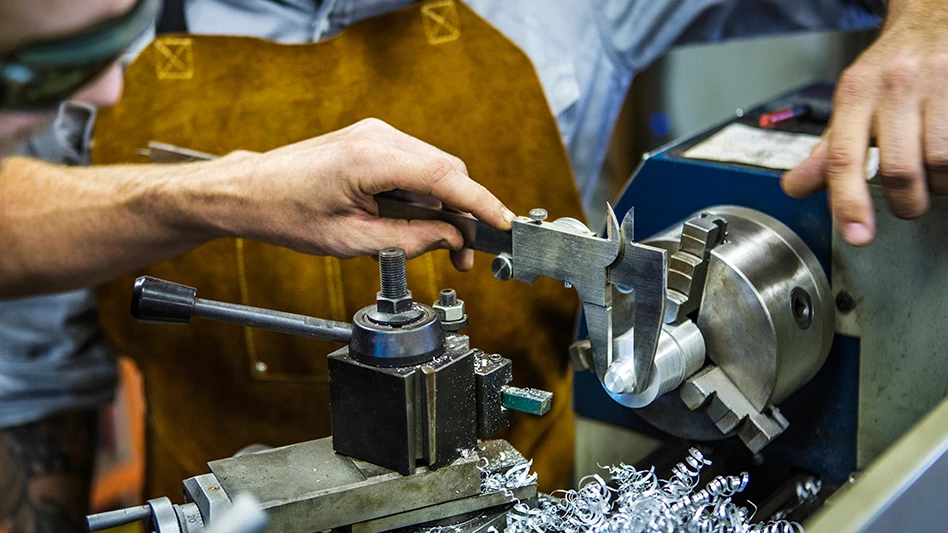
Machining components for medical devices is in many ways very similar to manufacturing parts for the aerospace industry. The materials titanium, stainless steel, cobaltchromium and other special alloys, and highperformance polymers are often the same. The requirements for dimensional and geometric precision and tightly controlled surface finishes are very similar. The parts themselves are often complex, thin, and very difficult to fixture while the features being machined can range in size from a few inches (centimeters) to a few hundredths of an inch (tenths of a millimeter).
While metals are chosen for medical devices for different reasons than they are chosen for aerospace components, their basic properties are the same in both cases. They tend to remain harder and stiffer than more common materials at the elevated temperatures generated at the tool/workpiece interface, and that produces high forces on the cutting edge during machining. Because they are quite strong to begin with, these materials also generate more heat when deformed during chip formation and because their thermal conductivity is relatively low, high cutting forces are generated even at low cutting speeds.
Compounding the challenge is the fact that these materials tend to work harden rapidly and the thickness of the work hardened zone typically exceeds the conventional tool feed rate. That means the tool is cutting continuously in material that is much harder than the nominal value for the workpiece material.
As a result, cutting edge wear tends to be rapid and it is difficult to maintain precision tolerances. High levels of residual stress can be generated in the component when using the wrong parameters. Cutting tools used on these materials tend to fail through edge chipping and/or substrate deformation.
Characteristics of Drilling Operations
Drilling in these materials introduces a whole new set of challenges that are inherent to the drilling process. For example, the surface speed at the exact center of a drilling operation is extremely low while the speed at the periphery may be quite high. Examination of a drilling edge that has been used on typical medical component materials will show two areas of heavy wear, one at the center and the other on the periphery.
The center wear is mainly due to a combination of low cutting speed and low temperature plus high hardness due to work hardening of the workpiece material. This condition is best countered by increasing the hardness of the drill material by using one of the newly developed carbides with submicron grain size.
Peripheral wear typically shows up as crater wear, flank wear, and deformation of the cutting edge. The high temperatures generated by the much higher cutting speeds encountered at the tools periphery cause all three conditions. This situation is best countered by protecting the drill with a thin, wearresistant PVD coating such as the TiN/TiAlN coating used on SecoCarboloy drills. The titanium nitride provides toughness and buildup resistance while the titanium aluminum nitride provides outstanding high temperature wear resistance.
Drill Geometry
Drill geometry is also very important in these materials. The best results are achieved with &dlquo;light cutting &drquo; tools having sharp edges and high clearance angles, yet the high forces encountered in these materials, particularly at the center of the drill, demand high strength as well.
One successful solution is found in the SecoCarboloy &dlquo;M &drquo; and &dlquo;T &drquo; drills that are designed specifically for these kinds of materials. They are made from submicron carbide with a very sharp 0.0005 &drquo; edge produced to very close tolerances by advanced manufacturing techniques. These drills have a 12degree front clearance angle, a minimum land width, and twice the back taper of a conventional drill all to reduce heat and minimize work hardening.
To illustrate the advantage of this geometry, in a drilling operation on a cobaltchrome knee stem, switching from a conventional drill to an Mdrill increased the number of holes per drill from 16 to 31 and saved the manufacturer more than $100,000 a year. In another case, changing from a conventional Seco drill geometry to a comparable Mdrill reduced cycle time by increasing the penetration rate while raising the number of holes per drill from 325 to 875 for an annual saving of $7,000 on Ti6Al4V and 316 stainless steel plugs. A third application on Ti6AL4V hip stems increased the holes per drill from 1,500 to 7,300 using the same speeds and feed rate.
Types Of Drills
For larger diameter holes, drills with indexable carbide inserts or drills with replaceable coatedcarbide crowns provide an excellent solution. The SecoCarboloy perfoMAX and CrownLoc lines are examples of these types of drills. Both have been applied successfully in the materials commonly used for medical components. One advantage of the perforMAX indexable drill is that the center insert can be of different material and geometry than the peripheral insert to help optimize performance at both extremes. Carbidetipped drills offer the benefits of low cost plus very rapid tool changes and cutting geometry substitutions.
Solid carbide drills should not be overlooked for applications of this type, particularly for the smaller hole sizes. Indeed, for really small holes solid carbide drills may be the only practical choice, but they also offer advantages in larger sizes. Among the most important of these is the potential to eliminate secondary operations such as reaming because the required surface finish often can be achieved with the carbide tool alone.
Milling Medical Materials
Milling of medical materials presents much the same list of challenges as drilling, and many of the same solutions apply. &dlquo;Light cutting &drquo; geometries, strong, sharp cutting edges, and careful grade selection are all important, as are setting optimum feed rates and depths of cut.
This is another area in which solid carbide tools ought to be carefully considered. In many cases a formground solid carbide mill is the best solution for producing complex parts, and not just in hard materials. This UHMPE knee insert shown here is a good example.
Here the critical requirement includes a carefully controlled 20 in. (0.50(m) surface finish in the critical bearing areas. The difficulty here is that the material stretches before it shears leaving an unpredictable irregular surface with many burrs on the periphery.The material also tends to wear cutting edges very quickly, despite its low tensile strength. This happens because the cutting action must break the long polymer chains of the materials composition rather than tearing them along grain boundaries, as is the case with metals.
The parts were originally machined with HSS profile cutters and special tools using solid carbide inserts, but the surface finish was unacceptable. A secondary soda blasting or manual polishing operation was required to meet surface specifications.
SecoJabro developed a solid carbide form tool produced with a special grinding process and edge geometry that yields an exceptionally sharp, stable, and smooth cutting edge to machine the critical bearing profile on the inserts. (Premier Finish procedure) With this tool, the customer consistently achieves a 15 to 18 in. (0.35 to 0.45m) surface finish with minimal burring.
The knee inserts are cut at 656 SFPM (200m/min) in production, although the cutters have produced the required finish at speeds up to 3281 SFPM (1000m/min) in laboratory tests. Feed rates are determined by cutter size, with 39 in/min (1000mm/min) being common for the cutters with diameters above .98 in. (25mm).
One interesting phenomenon encountered during the development of this application was the fact that any inconsistencies between the control signals and the milling machine response characteristics immediately showed up as irregularities on the part surface. It was necessary to carefully tune the control signals and the machine tool response so that all axes moved smoothly and consistently before the new tooling could be put into production.
In a more conventional application, SecoJabro also developed several special solid carbide milling cutters to improve the productivity of an operation producing hip cups from Ti6AlV4 forgings. Specifically, they optimized the milling operation that produced the antirotation tabs on the upper edge of the cup, developed a drill/mill that also produced spherical seats in each drilled hole, and designed a tool to backface all of the holes.
These tools replaced a series of standard mills and drills that had been used to produce the cup features in separate operations. The same drill/mill and backfacing cutters are used for all sizes of hip cups produced by the customer, further reducing production cost. Overall, the customer achieved a 30percent reduction in production cost and a 50percent reduction in tool cost.
The backfacing tool is particularly interesting. It is essentially a T slot cutter with a cutting diameter of .21 in. (5.4mm) capable of machining a .07 in. (1.8mm) maximum width land around the periphery of the hole on the outside of the part. The shank diameter of this tool is only .06 in. (1.6mm).
Special Requirements for SmallDiameter Tools
While the backfacing tool used on the hip cup is small by conventional standards, it is actually quite large in the world of microtools where solid carbide drills and endmills are available in diameters as small as .0024 in. (0.06 mm). Using these tiny tools successfully requires the right machine tool, and many changes to standard machining practices.
Probably the single most important requirement is a spindle capable of speeds up to 40,000 RPM. This is necessary because small tools must be rotated very fast to achieve acceptable cutting speeds. As a rule of thumb, 20,000 RPM is the starting point for hard materials in the 60 Rc range, while the same tool may require 40,000 RPM to perform successfully in a soft plastic like HDPE. Other materials will fall between those extremes.
Feed rates depend on RPM, tool length, and diameter, and are best determined in consultation with the tooling supplier. It is not a good idea to simply interpolate data from large diameter tools and apply it to small tools. Companies like SecoJabro who specialize in smalldiameter tooling have extensive databases of test results on a variety of materials to assist customers in establishing starting parameters for these operations.
Chip evacuation is also very important in smalldiameter machining operations. For most materials, air is the preferred chip removal medium. Two common exceptions to this are cobaltchromium alloys and Inconels on which fluid coolants are often used to control heat.
Spindles and tool holders must also be very accurate with minimal run out. A run out of 0.01mm is a full 10% of the diameter of a 0.1mm tool. Shrinkfit or precision collettype toolholders are preferred.
Thermal growth in the spindle must also be taken into account when using smalldiameter drills and other tools. As a spindle warms up it can experience Zaxis growth of anywhere from 0.01mm to 0.1mm. A 0.2mm miniendmill in that spindle will typically have a depth of cut of 0.03 mm in a hard material, and that much growth will surely break it.
Obviously, the machine tool must be very stable since even minor vibrations can damage a very small tool. Not as obvious, but equally important, control software must produce very consistent, uniform feed motions to prevent tool breakage.
Applying very small drills and end mills successfully is a matter of wellmastered knowledge of all the steps in the machining process. A cautious approach and careful record keeping are both essential elements in developing a successful application.

Explore the March 2005 Issue
Check out more from this issue and find your next story to read.
Latest from Today's Medical Developments
- NextDent 300 MultiJet printer delivers a “Coming of Age for Digital Dentistry” at Evolution Dental Solutions
- Get recognized for bringing manufacturing back to North America
- Adaptive Coolant Flow improves energy efficiency
- VOLTAS opens coworking space for medical device manufacturers
- MEMS accelerometer for medical implants, wearables
- The compact, complex capabilities of photochemical etching
- Moticont introduces compact, linear voice coil motor
- Manufacturing technology orders reach record high in December 2025