As minimally invasive surgical procedures grow in number and complexity, the demand for more sophisticated surgical instruments has grown even faster. Surgeons are demanding new and better-designed instruments that they can safely maneuver around, behind, and past organs, bones, and arteries while performing delicate tasks without causing injury while minimizing blood loss and pain.
 |
| Each bend or contour for a particular needle product requires a separate mandrel and a separate bending operation. |
Aiding the medical designer to achieve these goals are automated manufacturing processes that allow for the creation of precision rods and tubes with multiple contours, as well as with features such as shaped tips, slots, cross-holes, and grooves. Also designed specifically to meet this need are new computer numerical controlled (CNC) bending systems. Validated and certified, the new process benefits are many, including improved quality products, faster prototypes, faster production run turnaround, and lower costs.
Bending Origins
A brief review of the origins of wire and tube bending will give the medical designer insight into how the technology developed, as well as its current direction, enabling more sophisticated medical device designs.
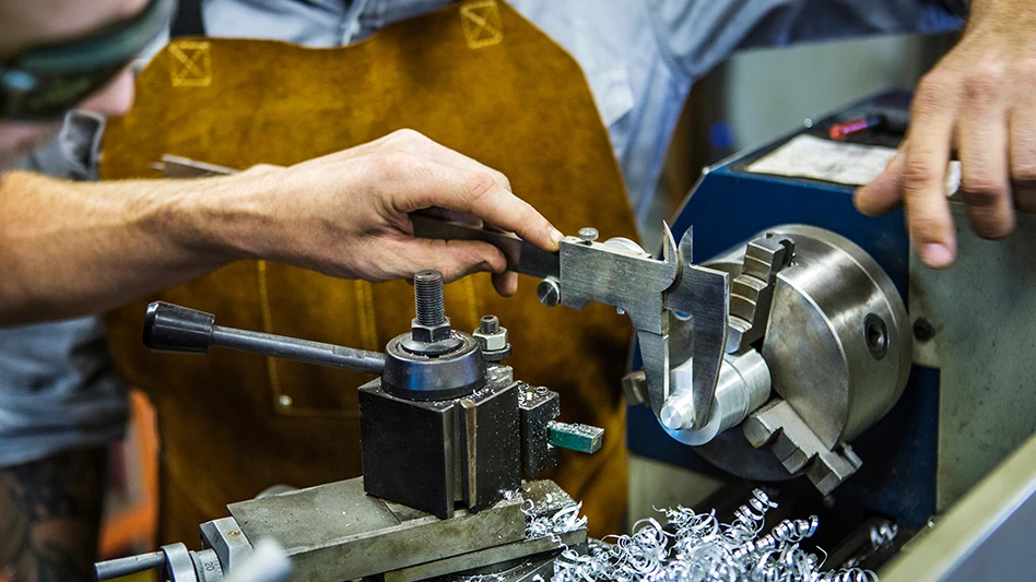
The earliest bent and contoured rod and tubular medical devices were produced using mandrel processes. For these applications, a mandrel is machined out of a solid block of metal into the near net shape of the desired bend features. The wire, tubing, or rod material is manually bent around the mandrel, using a tension roller to achieve the desired shape.
Utilizing the mandrel bending method, the initial mandrel size could only be estimated by evaluating how much spring-back the raw material displayed when performing a simple bending test. When taking the data from the bend test into consideration, the mandrel would be built at a calculated larger or smaller shape to compensate for the spring-back. Multiple parts would then be run on the mandrel and the parts would then be measured. If the parts would not conform to the required dimensions – which was often the case – a complete remake, or at minimum, a reworking of the mandrel was required to adjust the dimensions.
For complex 3D wire or tube designs containing compound arcs, multiple tooling iterations were often necessary. For example, every design, which required adding multiple-bend radii, also required that an additional mandrel and bending operation be performed. For each of the added bending opera tions, a separate inspection operation would also be required to ensure part acceptability before moving to the next operation. These subsequent bending operations also tend to reduce part consistency due to the need for re-clamping and other considerations, such as material heat lot variation.
The variation in material adds to the bending process complexity, often requiring re-working or re-building part mandrels. While the mandrel method was the best available process at the time, it had limitations. The bend results could vary from one material lot to another; consistency of heat-lot to heat-lot was difficult to achieve without usually having to modify the mandrels; and, as a result, production rates were slow, while at times, scrap rates were high. Now with the creative use of automated CNC bending, these problems and limitations have been overcome while providing a new range of design options.
Tips, Slots, and More
While the focus of this article is on the latest CNC tube and wire bending technology, many of these medical devices require additional precision features often produced following the bending operations. (The sequence with which these features are added to the bent tubes can alter the bend(s) and contour(s).) These features include precision cut-off, turning, and milling of special tips (trocar, bullet, barbed, pencil, etc.), cross-holes, grooves, and slots, all with very precise tolerances. These processes often include EDM (wire and plunge), flaring, swaging, and/or laser machining (cutting, welding, and marking).
In regards to the bending process, the process Marshall Mfg. utilizes is designed for bending wire and tubing after the parts are cut to finished length and fully machined, with the necessary part features as described above. This ensures the quality of the bend(s) and contour(s) are not compromised by later-stage operations such as re-clamping, machining, etc.
To acquire the largest and best arsenal of design options, today’s medical part designer needs to partner with a supplier having the latest capabilities and experience at providing all operations, not just the bending.
 |
| Medical devices often require bent tubes and rods with special tips, cross holes, detents, flats, and more. |
The Contoured Part
Computer numerical control (CNC), coupled with servo technology, is the key to today’s 2D and 3D medical device tube and wire bending. Marshall’s CNC technology allows for programmable bending that is precise and predictable, producing prototype and production run quantities with repeatable quality.
During the design stage of a particular tube or wire medical device, it is often difficult to describe the bending requirements. The desired touch, feel, and other sensitivities of the instrument are often difficult to imagine, articulate, and even more difficult to quantify. The design often requires certain features of the part to be oriented to other features after bending. Having bending expertise and the ability to provide quick design iterations is critical to the customer getting what they want.
Once these customer requirements are understood and articulated through an iterative prototyping process in the CNC bending system cell, sample parts are produced quickly and with minimal, and sometimes no, tooling costs. Once a particular bend design is accepted, the CNC bending systems will consistently repeat the bend features. Additionally, going from prototype to production quantities results in a huge time compression for even greater economies.
Equally important with these CNC bending systems, where heat lot differences or other minor variations in material consistency are experienced, major tooling overhaul is no longer required as was the case with the previous mandrel method of production. Modifications of the CNC program can quickly compensate and correct any variations in material consistency.Prototyping, Production Once the part program is established and proven, setup consists mainly of loading raw material into the system. In the system featured in this article, forming tube diameters range from 0.096" to 0.375" and wire ranges from 0.080" to 0.200" in diameter. Length capacity for both wire and tubing ranges from 5-3/4" to approximately 60".
All aspects of the automated cell are designed for maximum flexibility while keeping production costs low. The cell moves raw pre-bent parts through the entire production cycle without operator intervention. Three phases to the bending cycle include:
1. Preparation – Straight wires or tubes are staged for bending. The cell features a stock magazine that stores raw parts waiting to be bent. The magazine is capable of holding hundreds of pre-bent parts requiring minimal operator time for loading.
Once loaded, a robotic arm removes a single part from the piece separator in the magazine. The robotic arm has custom designed grippers that pick up and grasp the part at a specific location along the part. Customer requirements often dictate that a part feature – machined flat area or drilled cross hole, for example – must orient to other part features after bending. The cell has the ability to orient the part as needed, utilizing laser or other custom-sensing devices. Once oriented, the robotic arm moves the part to a second staging area near the bend tooling where it is clamped in place. The robotic arm may re-grip the part when needed, allowing full range bending along the part length.
2. Bending – During the bending process, a series of rollers act as virtual mandrels. There are two types of bending modes in this system: free form bending and rotary draw bending. In free form bending, the wire, or tube, is pushed through two or more rollers – taking the place of the mandrels in manual bending. These rollers put pressure on the sides of the part, in a right or left direction, to produce the desired curves. In unison with the series of rollers, the part can be turned while passing through the rollers, in order to produce 3D helixes, curls, and other desired shapes.
In rotary draw bending, the wire is pulled around a mandrel, instead of being pushed through by the robotic arm. This method is utilized when a simple curve is required. When needed, both free form bending and rotary-draw bending are utilized in this system for processing a single part. Parts with multiple bend radii are formed easily and quickly in this system, instead of needing one mandrel for every individual bend.
Making slight changes to a straight length, a bend radius, or the pitch of a helix shape is easily achieved by making changes in the CNC program. This adjustment is ideal when developing prototype parts and for providing a controlled range of variances in the part to narrow down and achieve the desired bending outcome. This system can also be programmed to fabricate consecutive mirrored image parts – a right hand part followed by a left hand part, or a top part followed by a bottom part.
3. Finished part handling – Medical device manufacturing requires special consideration of finished part handling. Rough handling can cause surface imperfections or other visible marks. The CNC system, discussed in this article, is designed to eliminate the possibility of mishandling of parts while providing real-time part inspection without interrupting cell operation.
Customer requirements as well as the mechanical properties of the part material dictate part handling requirements. These will vary by part project requirements. Certain parts may require parts to be gently set into a lined container and removed immediately to eliminate part-to-part contact and possible damage. Another part style could require staging for further operations onto a conveyor belt. More robust parts – for example, pre-heat treated – may be dropped directly into a bin. With this CNC bending system, the robotic arm handling the part throughout the bending portion of the process can also be programmed to place completed parts into a predetermined location.
Since there is no operator intervention between material loading in the stock magazine and part ejection, the cell allows the operator to check finished parts while operating, without interrupting the system, further reducing part cost while improving delivery.
Click here to watch a video where Marshall Manufacturing Co. demonstrates bending medical devices using CNC machinery.
Marshall Mfg. Co.
Minneapolis, MN
marshallmfg.com

Explore the October 2010 Issue
Check out more from this issue and find your next story to read.
Latest from Today's Medical Developments
- NextDent 300 MultiJet printer delivers a “Coming of Age for Digital Dentistry” at Evolution Dental Solutions
- Get recognized for bringing manufacturing back to North America
- Adaptive Coolant Flow improves energy efficiency
- VOLTAS opens coworking space for medical device manufacturers
- MEMS accelerometer for medical implants, wearables
- The compact, complex capabilities of photochemical etching
- Moticont introduces compact, linear voice coil motor
- Manufacturing technology orders reach record high in December 2025